
Dec 5, 2011 , by
Public Summary Month 12/2011
The tests and framework studies that have been done in the last two months, belong partially to Task 2 (Positioning/Relocation), partially to Task 3 (Site Tolerance) and partially to Task 4 (Material Tolerances). Current stage of the project requires an integral progress on all of these 3 tasks and it aims proving the steps of the hypothesis developed for the final demonstration. Based on the theoretical study/literature survey on robots in construction sites two hypothetical scenarios were developed for two different cases, and a hypothetical framework (Fig 1) was set for these two scenarios. Both of the scenarios involve building a modular wall with the robot on the construction site either with reference to existing elements in the workspace or in an undefined workspace.
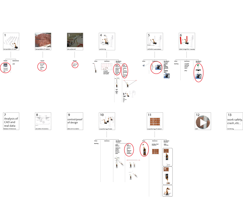
Fig. 1: Hypothetical framework set for the two scenarios developed
Setting a hypothetical framework clarified all the steps to be taken from start to end for the developed scenarios. Depending on the scenario chosen, hardware, method of data handling, utility and controlling mechanism changes.
Description of the Hypothetical Framework
As it can be seen in Fig 1, framework consists of the following stages:
- Transportation of robot to construction site,
- Transportation of material to construction site,
- Preparing the set-up (power),
- Positioning
- Calibration (3-point calibration)
- Object recognition / measuring
- Feedback of tolerances
- Calculation of solutions
- Data communication
- Re-positioning of robot
- Re-positioning of material
- Starting to build
- Monitoring
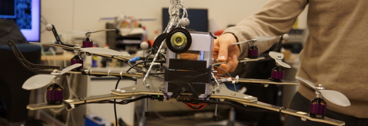
Tests on Self-Orientation
In this test, 3D scanner is programmed to measure 3 taught points from the tilted wooden board and by drawing a plane through these points, it finds the right orientation for the gripper.
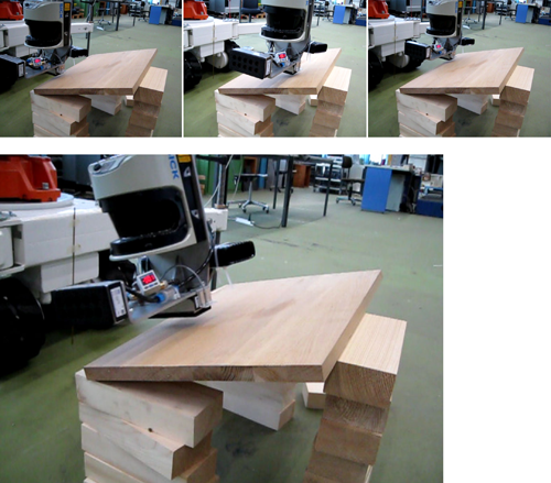
Fig. 2: 3D scanner is programmed to measure 3 taught points from the tilted wooden board and by drawing a plane through these points, it finds the right orientation for the gripper
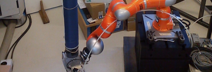
Tests on Self-Positioning
The 3D scanner which was implemented on the robot was also used to test self-positioning with the help of a metal disk whose central point was used as a reference marker (satellite). With the satellite, robot will be able to move several times, re-positioning itself according to the measured coordinates of the center point of the satellite.
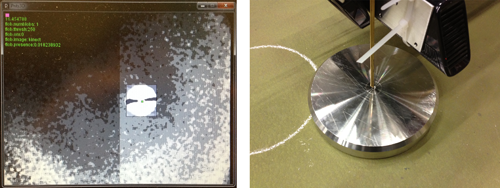
Fig. 3: A 3D scanner attached to the gripper of the robot finds/measures the center point of the steel disk (satellite) and gripper moves to that measured point accordingly
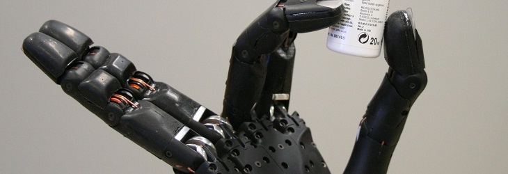
Tests on Material Gripping
Tests done on material gripping cover trying out the material size that is being planned to be used in the final demonstration, and building a material dispenser out of aluminum profiles integrated to the robot. This material dispenser is adaptable to different material sizes and attached to the robot.