
Aug 27, 2012 , by
Public Summary Month 7/2012
Taks 7: System testing
Within our last experiment steps we evaluated and optimized the entire robot system. In the first step we examined the object recognition and position estimation of Camera A. The camera configuration and image processing were improved until the derivation did not left a range of ±50mm. In the next step we examined the positioning of the gripper. The system was improved until the deviation may amount to only ±5mm, so that the pick procedure can be done successfully.
After the evaluation of the cameras and image processing, we optimized the position control of the robot to improve the repeatability. After optimization we arranged the scenario as it was introduced in the proposal with a set of three different tagged cubes. In several repetitions we diversified the position of the cube in the range of Camera A, in order to determine the reliability of the system. The experiment was considered as final, as soon as the system was able to grip tagged objects in its vision range and deposit these objects in a defined target position.
Furthermore we arranged a second scenario in that small cylinders with a through-hole were threaded onto a needle. Here, the dimension of a single cylinder was 10x5mm (height by diameter) and the mentioned through-hole had a diameter of 3mm. The robot was able to thread all cylinders onto the needle, which verified a repeatability of ±1.5mm.
Taks 8: Dissemination
In the last two experiment month, the most important dissemination activities were:
- The Multimeda Report was created and is now available here: http://www.youtube.com/watch?v=o94NYrFNRmo
- We preparing the last presentation about our ALEXA experiment that will be given at the IROS 2012 during the ECHORD workshop. The workshop schedule is available here: http://echord.info/wikis/website/iros-2012-workshop
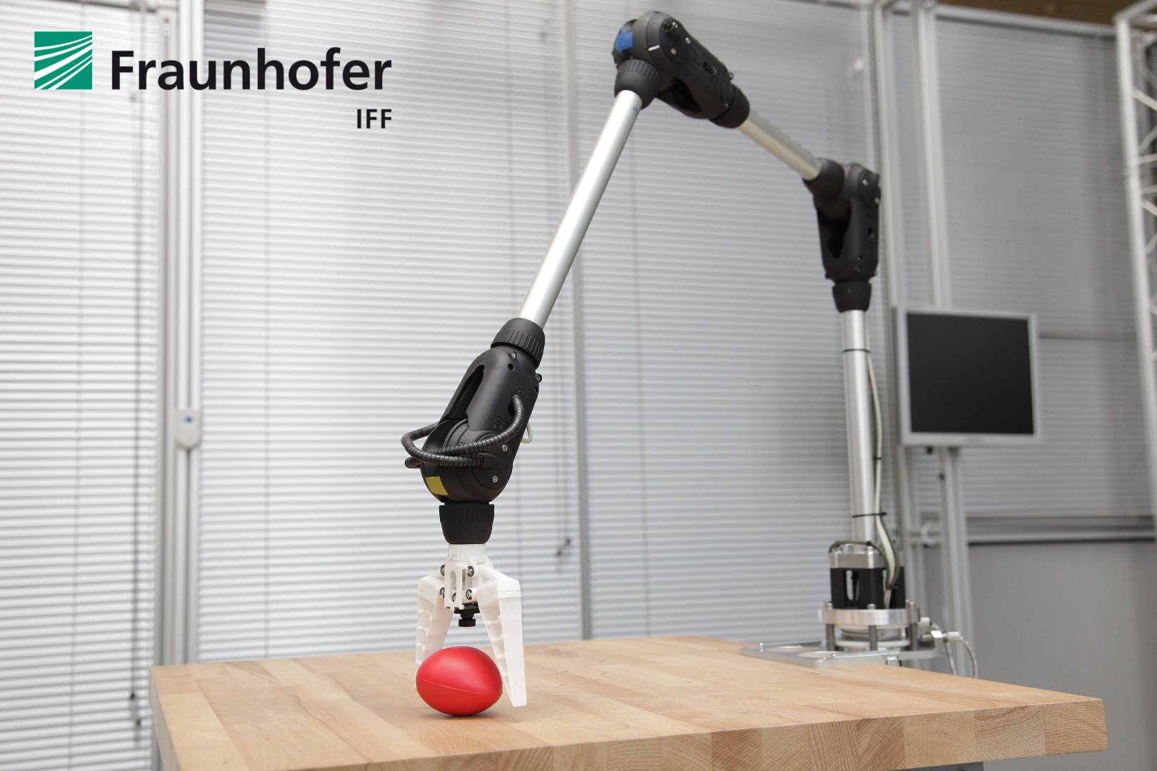
Photographs of the ALEXA robotic arm
.jpg.html)
.jpg.html)
.jpg.html)
.jpg.html)
.jpg.html)
.jpg.html)
Jun 29, 2012 , by
Public Summary Month 6/2012
Experiment Progress
- The camera system was finally mounted and calibrated
- The first system test was arranged for our exhibition at the Automatica in Munich. The scenario consists of a simple sorting application.
- The ALEXA robot was a part of our exhibition under the topic of “Safe Manipulators for Human-Robot Interaction” among other exhibits as innovative safety sensors and technologies. The feedback from our visitors was consistently good.
- We begun to arrange the final scenario
- We had a talk at the ICRA 2012 in St. Paul during the ECHORD Workshop. The talk was about our main results of the ALEXA experiment.
Next steps
- Evaluation and testing of the entire robot system.
May 2, 2012 , by
Public Summary Month 5/2012
Task 5 - Implementation of Visual Servo Control
A full-implementation of visual servo control functionality turned out to be more complicated as expected. High performance losses in the Bowden-cables due to friction effects compel us to reconstruct the drive system in a radical manner. Due to the reconstruction of the drive coupling, there is unfortunately not enough time left to implement visual servo control with all functionalities. For that reason, we decided to downgrade the visual capabilities of the ALEXA robot.
Task 6 - Construction and calibration of the camera system
As presented in our concept, we are using two color cameras. The first camera is mounted on the first link. It is provided for object recognition and position estimation. The second camera is located in the gripper. It is provided for precise position determination. All cameras were successfully installed.
Task 7 - System Testing
We will present our ALEXA robot on the AUTOMATICA trade fair in Munich at hall B3 booth 510. The public presentation will show some capabilities of the robot that we will also show with the final experiment setup. Further, this scenario allows us for a first system testing. It will show how the ALEXA robot is working in industrial applications.
Further Occurrences
We wrote a paper with all important results of our ALEXA experiments. The paper is the first of at least two. It was accepted for the ECHORD workshop that takes place at the ICRA 2012 in St. Paul, USA.
Feb 6, 2012 , by
Public Summary Month 1/2012
Task 4
We finalized the main control of the ALEXA robot. Finally, it has the following features:
- Functionalities to compute paths with minimal joint loads (PTP motions) and in optimum time (LIN motions)
- Generator that computes position and velocity trajectories in the joint space
- Decentralized position controllers that combine motor and joint states to reduce the elastic effects of the actuation ropes
Furthermore, we optimized the position controllers to improve the motion capabilities of the robotic arm. In parallel, we developed a new feedforward controller that adjusts the rope tension of the respective actuated joint to an operating value.
Task 5
In early December of 2011, we began to implement the image processing modules for marker and object recognition as well as visual servoing functionalities. The implementation is currently in progress. In the following month, we plan to finalize the implementation. Afterwards, we will commission the mentioned modules and run some test to evaluate them.
Task 6
In December 2011, we constructed a mounting system to attach common cable channels and the multi camera system on the stiff links of the robotic arm. Further, we produced all mounting components and installed them on the robotic arm. Currently, we renew the pull-through of all sensor and camera cables as well as its plugs. In the next step, we will commission and calibrate the camera system.
Dec 7, 2011 , by
Public Summary Month 11b/2011
Task 3
During the first all-over motion test, we find out that the load torque of some drive motors reached a critical value. The reason here was the high friction in the Bowden cables and in the rope lead-throughs. To reduce the friction influence, we assembled Teflon coats over the related ropes for better frictional properties. After that we ran a new all-over motion test. This time, the loads of the drives were obviously lower.
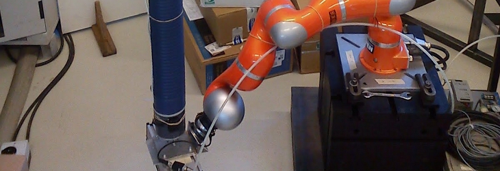
Now, the entire robotic arm and its compact drive unit is completley built-up and finalized. The ALEXA robotic system is shown by Figure 1 to Figure 4.
![]()
Figure 1: ALEXA robotic arm
![]()
Figure 2: Compact drive unit
![]()
Figure 3: Detailed view of the rope actuating drives manufactured by Schunk
![]()
Figure 4: Wrist joint
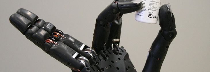
Further, we constructed a lightweight gripper that can be actuated by a rope. The gripper is made out of Polyamid 12 and was produced in Rapid Prototyping techniques. Furthermore, we used compliant fingers with FinRay design manufactured by Festo. A socket for the camera was also integrated.
Task 4
The implementation of the main control system is almost finished. The main control system includes a software system that controls the drive motors, plans optimized trajectories, acquires all sensor data and avails image processing interfaces. Now, we debugging all software parts and searching for optimization potentials.
Task 5
We began to prepare all existing software modules for image processing and object recognition to link with the interfaces of the main control software. After debugging and optimizing the main control software is finished we will implement the visual servo control algorithms.