
Oct 18, 2013 , by
Public Summary Month 10/2013
9th Public Report:
The complete robot system is currently being integrated. The mobile column was constructed, manufactured and assembled (see Figure 3). It is capable of carrying the two robot arms, their controllers and powers supplies. The construction is very solid designed (over 250 Kg) and with the centre of gravity being located very low over the ground to prevent it from tilting over. The power supplies etc., the controllers, cameras and emergency chain components have been integrated in the column. Also a switch was integrated to reduce the number of Ethernet cables going from the control pc to the robot column.
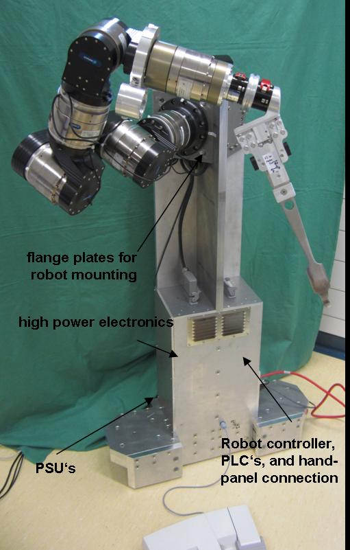
Figure 1: Mobile robot column with the location of the integrated components shown.
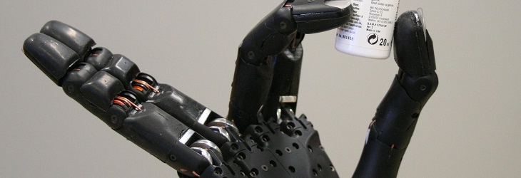
The new gripper (for the construction see report no. 8) was manufactured (see Figure 1). To allow the retractor to be coupled to the robot, a retractor adaptor was manufactured that also carries the ALVAR marker. The retractor adapter can be mounted on a standard medical retractor. The gripper allows a fast coupling of the retractor.
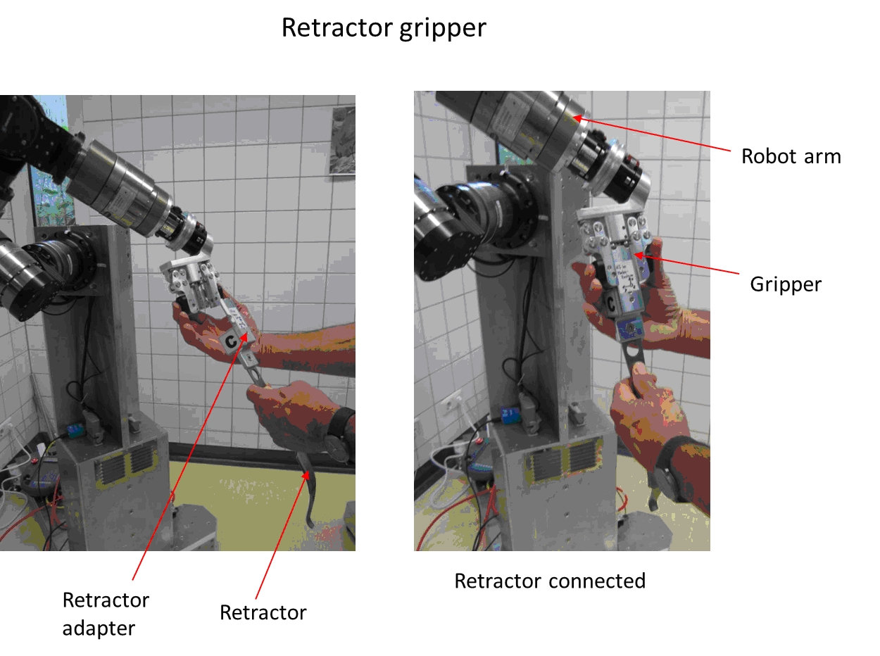
Figure 2: On the left side the retractor with retractor adapter and ALVAR marker moved towards the gripper can be seen. On the right side the closed gripper with the retractor is shown.
Jun 3, 2013 , by
Public Summary Month 5/2013
8th Public Report:
The complete robot system is currently being integrated. A movable column, capable of carrying both robot arms, their controllers and powers supplies was constructed, most parts have been fabricated in the workshop and the assembly has begun. The power supplies, the controllers, cameras and emergency chain components will be integrated in the column.
New USB-to-CAN interfaces were acquired and the drivers were integrated in ROS framework, excluding the necessity for a second workstation just for interfacing with the F/T Sensor.
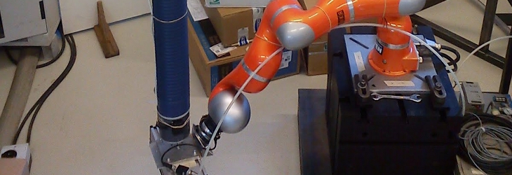
A preliminary algorithm was developed to hold the tool after the surgeon couples it to the gripper. It only rotates the retractor around a bone axis keeping the tip fixed, but it showed us that the robot responds well to changes of the external forces, moving the tool in a smooth manner (Figure 1).
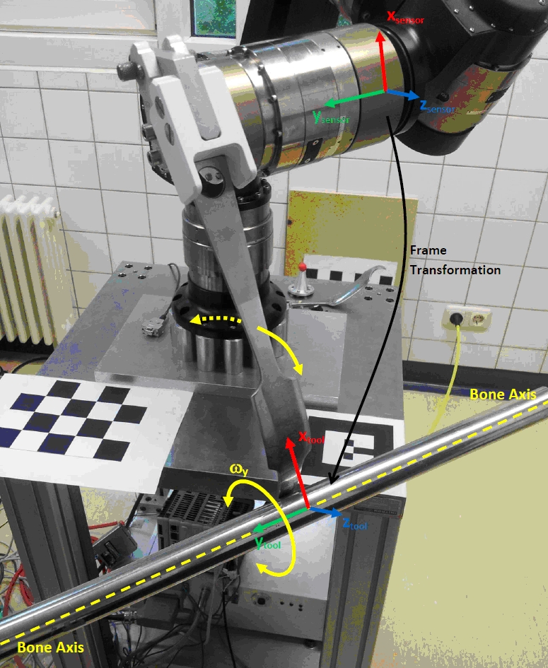
Figure 1: Current configuration and movements performed by the robot while holding the retractor (current algorithm only allows rotations around a bone axis).
Mar 27, 2013 , by
Public Summary Month 3/2013
7th Public Report:
An interface between the FT-sensor and Control PC was established, which enabled us to read the output data of the sensor. With that, the Force-Free Guidance mode was implemented. The user is now able to move the robot freely with his hands in a smooth and precise manner. This method enables the surgeon to manually align the gripper with the tool with high precision, as an alternative to the autonomous method (based on the tool tracking algorithm).
For the camera system, we had to calculate the extrinsic calibration. This was done with a flat checkerboard pattern on the base of the robot. The calibration was quite precise; however we will try to assemble a more appropriate marker, but for now it proved to be sufficient.
The approach of the robot to the tool had been previously done in simulation. Now, with the robot ready and camera calibrated, we could finally do it in the real world, with a maximum error of ~1cm. Thus an enhancement of the precision seems to be necessary.
Jan 31, 2013 , by
Public Summary Month 1/2013
6th Public Report
Robot and controller were successfully set up and work as desired now (Figure 1). To improve the robot movement while holding the retractor tests on a phantom simulator on site were performed to evaluate necessary parameters for the control to achieve a smooth movement [Results Submitted, CARS 2013, Gundling et al. Title: Phantom simulator for retractor holding tasks in robot assisted hip surgery].
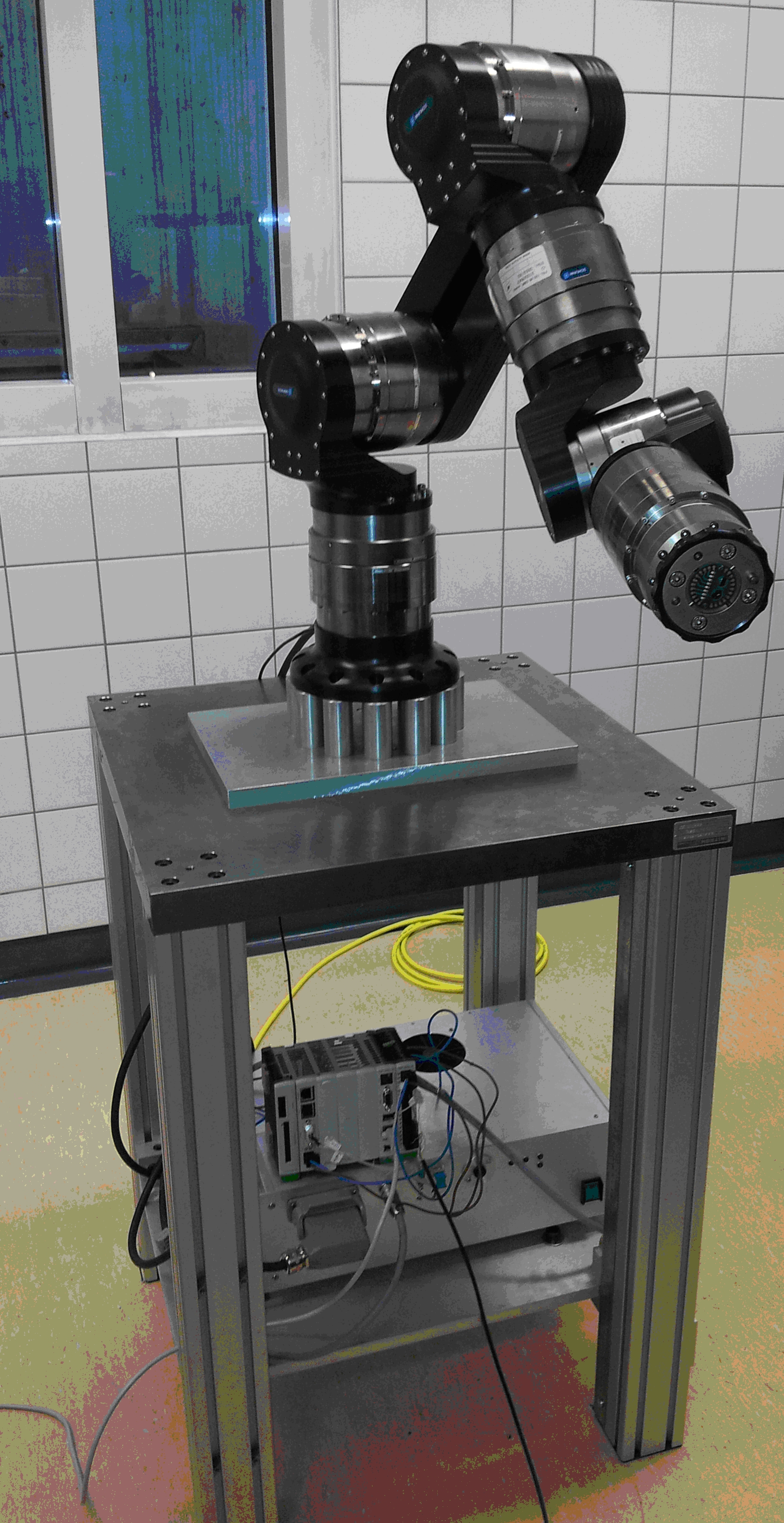
Fig. 1: Schunk lightweight robot arm mounted on a massive column.
Nov 28, 2012 , by
Public Summary Month 11/2012
5th Public Report
Improvements have been made to the F/T free mode in order for the robot to move more smoothly. Holding mode also needs to be improved since the movement is not smoth.
A collision detection algorithm has been implemented in order to prevent collisions between the robot and the objects/people in the environment and with itself. During simulated tests, the system has proved capable of stopping the robot automatically before hitting objects (Figure 1). Improvements can still be made since the collision map is not updated in real time while the robot is moving.
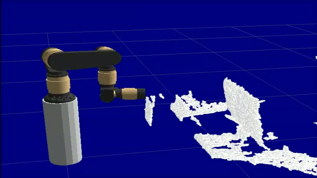
Fig. 1- Simulation of the Schunk lightweight robot arm approaching an obstacle detected by the camera system.
Although the real robot is not assembled yet finally, most of the control modules are present and have been partially developed and tested successfully in simulation mode, so their integration in a main control program has started.